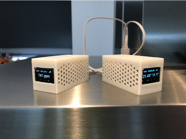
Following the ESPHome introduction, we use the Winsen CO2 sensor to measure indoor CO2 level. For reference look at the datasheet.
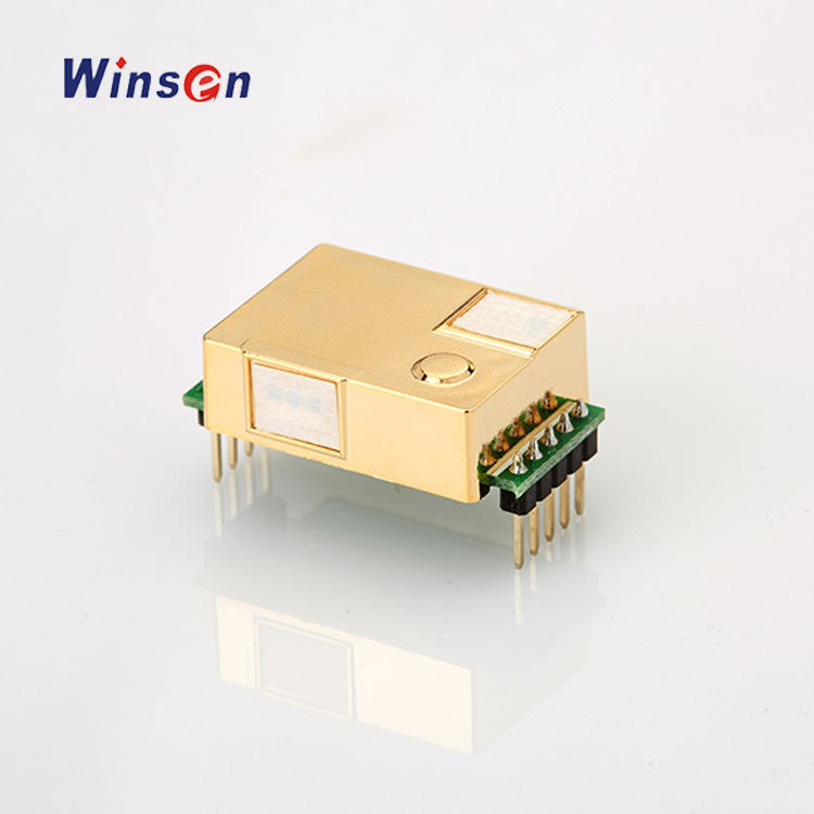
The sensor outputs the measured CO2 level in a PWM signal and a UART (serial) stream. We will use the UART interface in our example.
Connection
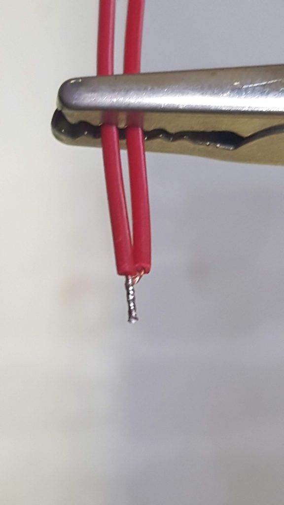
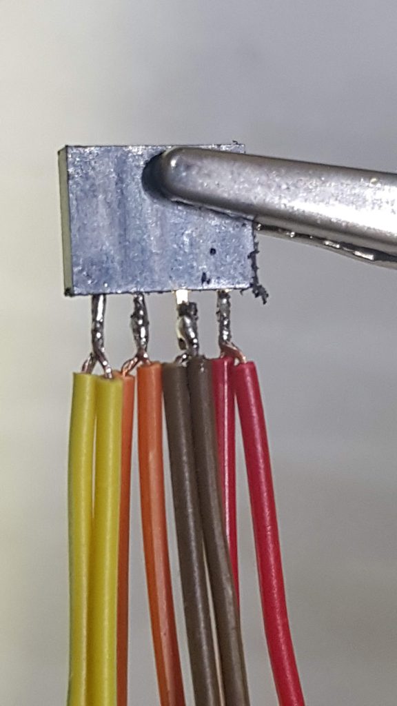
We need four connections: power (5V – 150mA, GND, Rx and Tx). If you use the sensor with the JST6 cable you can solder plugs on these wires, or use Dupont crimp connectors. In the case you solder them you can connect Red / Black (Power) to one 2 pin female header, and Blue/Green (Rx/Tx) to another 2 pin header as shown.

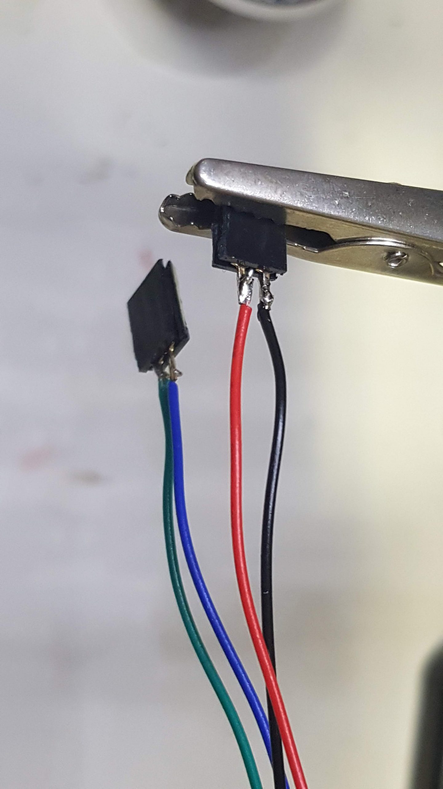
Both on Wemos D1 and NodeMCU v2 the 5V power line (or Vin) is besides Ground (or ‘G’). Connect the power connector according to the colours (5V is Red, Ground is Black).
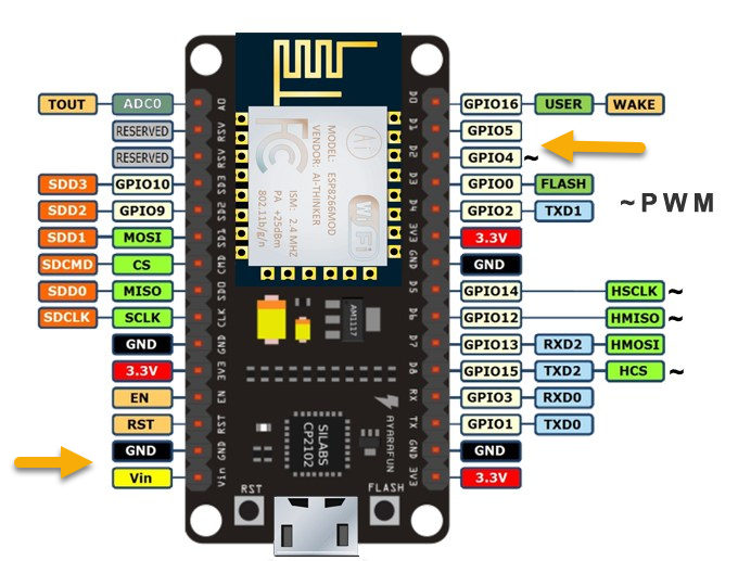
The Rx / Tx lines are connected to D1 (GPIO5), Green, Tx from module and D2 (GPIO4), Blue, Rx to module.
YAML file
We will use ESPHome for the software. If you are not familair with ESPHome, have a look at our previous workshop. Now we can add the sensor and the UART to the YAML file. First we will activate the uart. Feel free to use other pins if you use another ESP module.
#D1: Green Wire / mhz19
#D2: Blue Wire / mhz19
uart:
  rx_pin: D1
  tx_pin: D2
  baud_rate: 9600
We will add the MHZ sensor just before the BME280 sensor. There can only be one ‘sensor’ section! The sensor has also a temperature sensor, we will not use it here. More details on the ESPHome site.
sensor:
  - platform: mhz19
    co2:
      name: "MHZ19 CO2 Value"
      id: co2value
    temperature:
      name: "MH-Z19 Temperature"
    automatic_baseline_calibration: false
    update_interval: 60s
If we upload our code, the ESP will initialize the sensor and read the values. They are also available at the webinterface and will be published on the MQTT chanel if you activated this.
Add a display
To show the values on a small I2C display, we first have to connect the display to the I2C bus. That is a challenge, because the BME280 sensor also shares this bus. On a breadboard it is easy to connect both the Display and the BME280, if you want to solder you have to create a ‘splitter’. This can be done by soldering, or with crimp connectors.

GND should be connected to G or Ground, VCC to the 3V power line (some displays will accept 5v as well). SCL to D6 (GPIO12) and SDA to D7 (GPIO13). I2C was already installed in our previous YAML experiment. We will need a font, which can be downloaded here. You are free to download other fonts and experiment with a nice layout.
i2c:
  sda: D7
  scl: D6
  scan: True
 font:
  - file: "BebasNeue-Regular.ttf"
    id: slk
    size: 20
  - file: "BebasNeue-Regular.ttf"
    id: bebas
    size: 48
  - file: "BebasNeue-Regular.ttf"
    id: bebas20
    size: 20
 display:
  - platform: ssd1306_i2c
    model: "SSD1306 128x64"
    reset_pin: D0
    address: 0x3C
    id: my_display
    pages:
      - id: page1
        lambda: |-
          it.print(0, 1, id(slk), "CO2 PPM");
          if (id(co2value).has_state()) {
            it.printf(0, 15, id(bebas), TextAlign::TOP_LEFT, "%.0f", id(co2value).state);
          }
Complete YAML file
To experiment, the complete YAML file can be downloaded here.
Captive Portal
If you do not know the WiFi network at compilation time, you may use a ‘captive portal’. If the given WiFi network was not found, your node will start as an access point with the given credentials. You can connect with your phone or PC, go to 192.168.4.1 and enter the right credentials. They will be stored until the next upload of your program.
wifi:
  ssid: !secret wifi_ssid
  password: !secret wifi_key

ap:
    ssid: "CO2 meter"
    password: "1234abcd"

captive_portal:
Casing
Stefan has created a nice casing for this module. Details can be found here. In the written setup ‘ESPEasy’ is used to connect the sensor. Feel free to use this, or the ESPHome implementation.
