Categorieën
Workshop

ESPHome – CO2 sensor

Following the ESPHome introduction, we use the Winsen CO2 sensor to measure indoor CO2 level. For reference look at the datasheet.

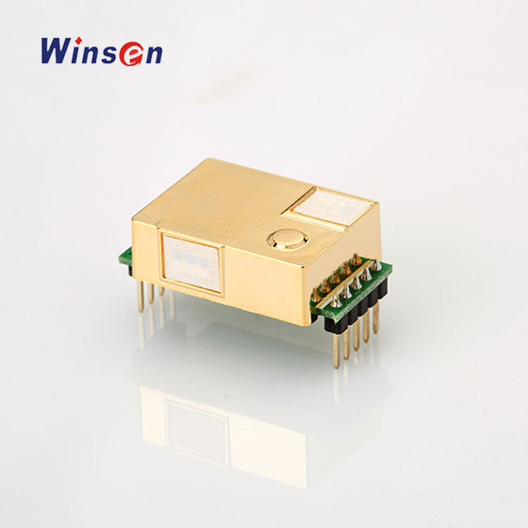
The sensor outputs the measured CO2 level in a PWM signal and a UART (serial) stream. We will use the UART interface in our example.

Connection

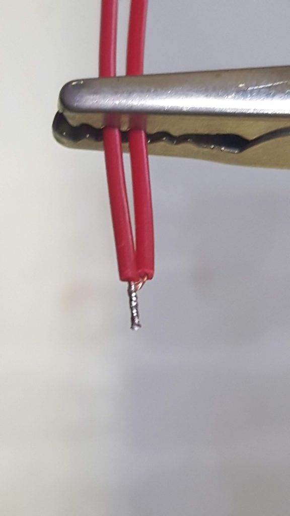
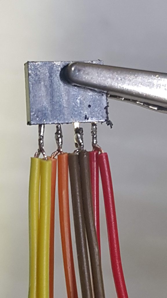
We need four connections: power (5V – 150mA, GND, Rx and Tx). If you use the sensor with the JST6 cable you can solder plugs on these wires, or use Dupont crimp connectors. In the case you solder them you can connect Red / Black (Power) to one 2 pin female header, and Blue/Green (Rx/Tx) to another 2 pin header as shown.

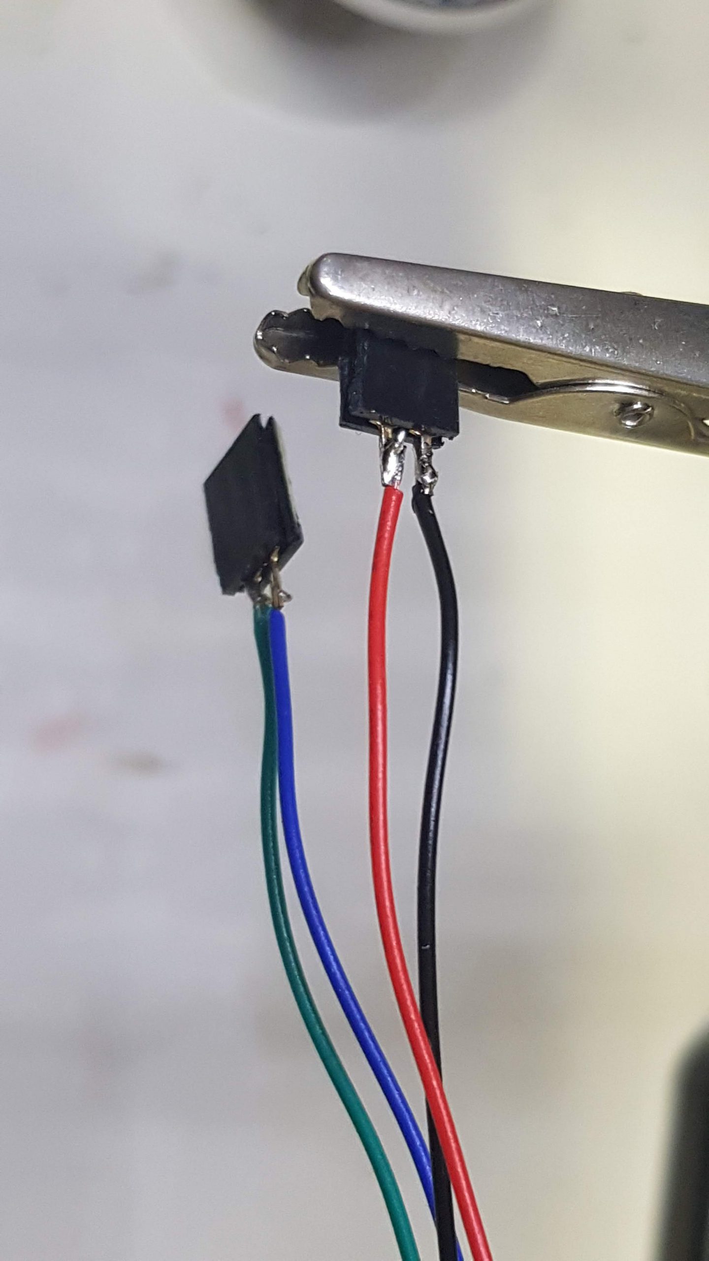
Both on Wemos D1 and NodeMCU v2 the 5V power line (or Vin) is besides Ground (or ‘G’). Connect the power connector according to the colours (5V is Red, Ground is Black).

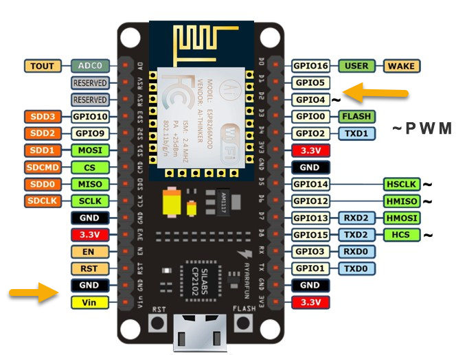
The Rx / Tx lines are connected to D1 (GPIO5), Green, Tx from module and D2 (GPIO4), Blue, Rx to module.

YAML file

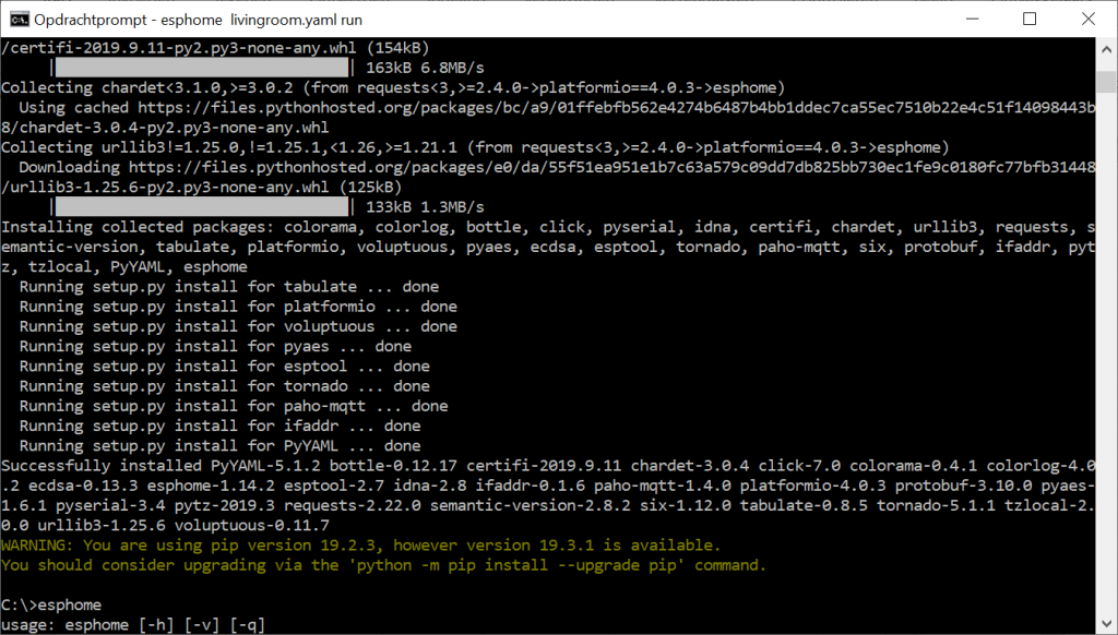
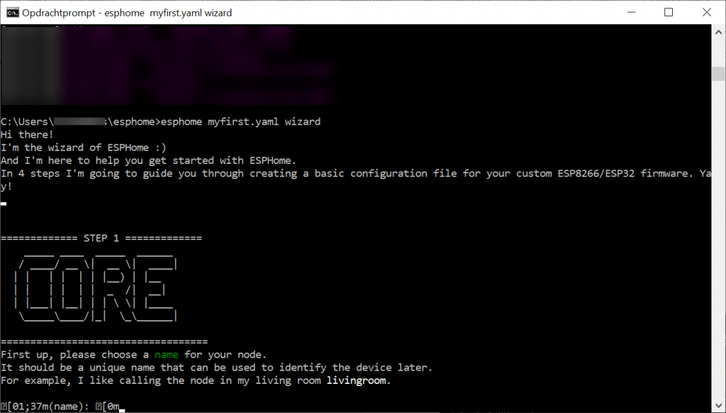
We will use ESPHome for the software. If you are not familair with ESPHome, have a look at our previous workshop. Now we can add the sensor and the UART to the YAML file. First we will activate the uart. Feel free to use other pins if you use another ESP module.

#D1: Green Wire / mhz19
#D2: Blue Wire / mhz19
uart:
  rx_pin: D1
  tx_pin: D2
  baud_rate: 9600

We will add the MHZ sensor just before the BME280 sensor. There can only be one ‘sensor’ section! The sensor has also a temperature sensor, we will not use it here. More details on the ESPHome site.

sensor:
  - platform: mhz19
    co2:
      name: "MHZ19 CO2 Value"
      id: co2value
    temperature:
      name: "MH-Z19 Temperature"
    automatic_baseline_calibration: false  
    update_interval: 60s 

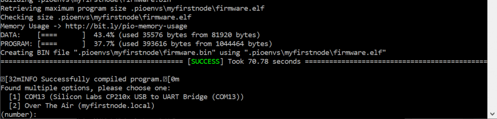
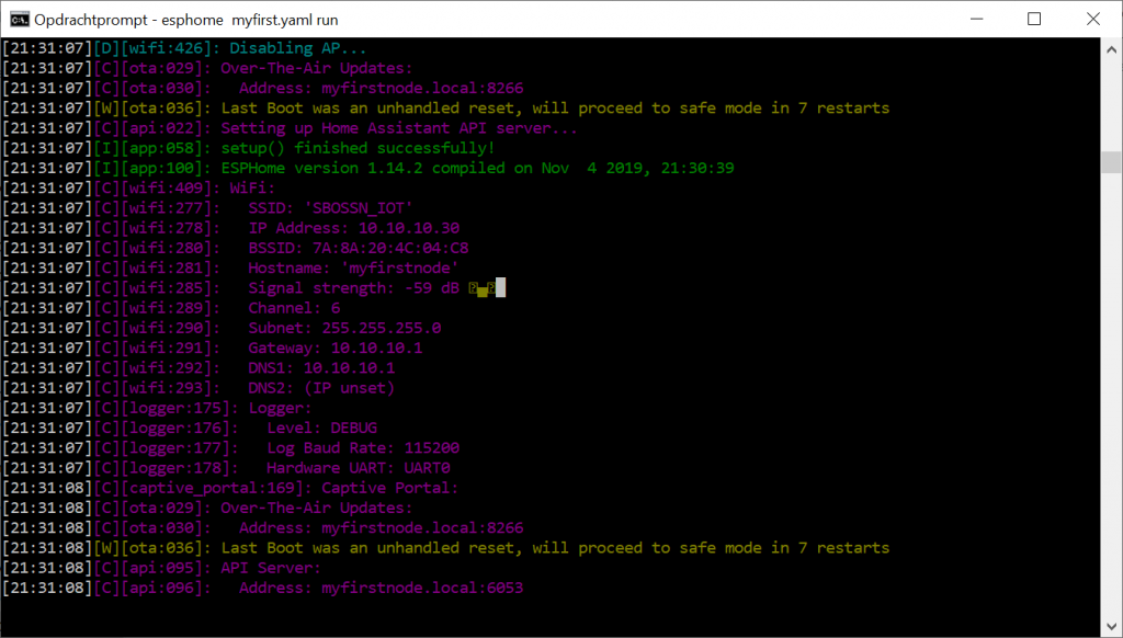
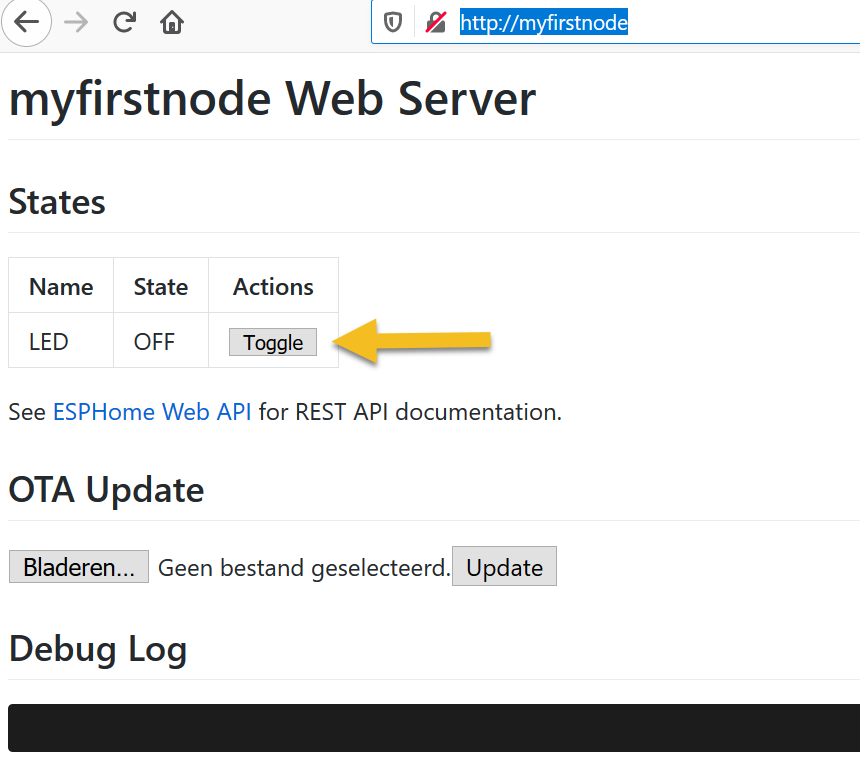
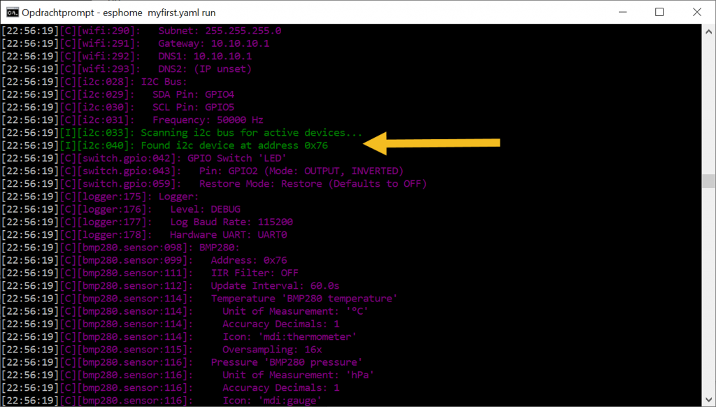
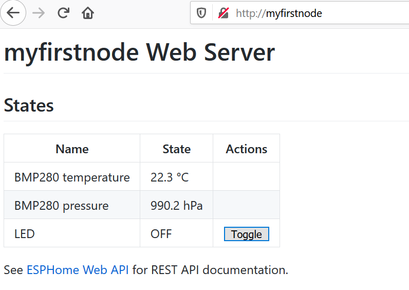
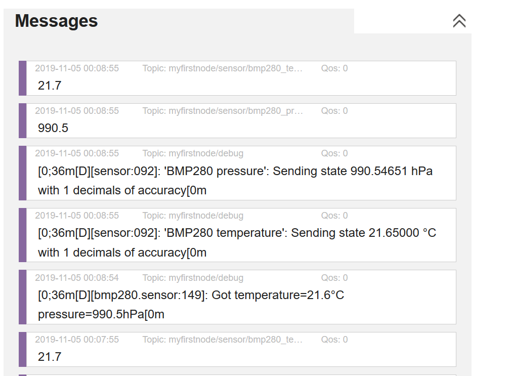
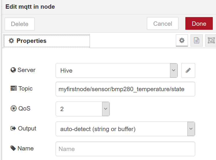
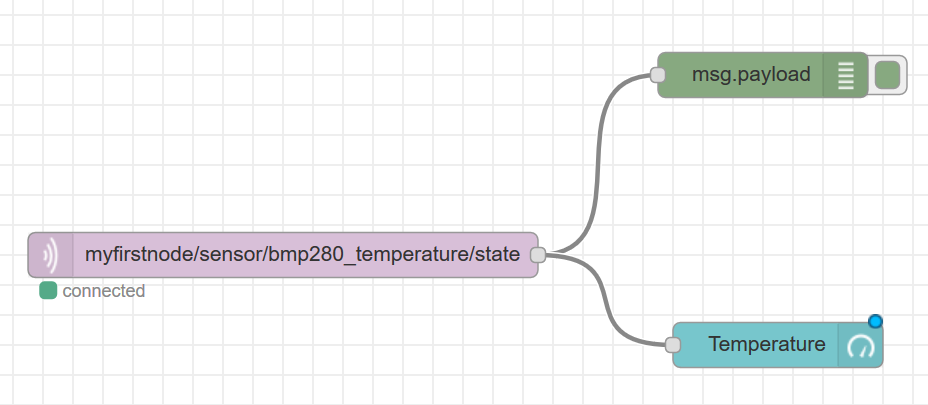
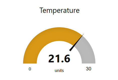
If we upload our code, the ESP will initialize the sensor and read the values. They are also available at the webinterface and will be published on the MQTT chanel if you activated this.

Add a display

To show the values on a small I2C display, we first have to connect the display to the I2C bus. That is a challenge, because the BME280 sensor also shares this bus. On a breadboard it is easy to connect both the Display and the BME280, if you want to solder you have to create a ‘splitter’. This can be done by soldering, or with crimp connectors.

Afbeeldingsresultaat voor ssd1306

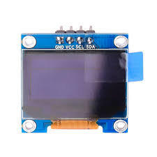
GND should be connected to G or Ground, VCC to the 3V power line (some displays will accept 5v as well). SCL to D6 (GPIO12) and SDA to D7 (GPIO13). I2C was already installed in our previous YAML experiment. We will need a font, which can be downloaded here. You are free to download other fonts and experiment with a nice layout.

i2c:
  sda: D7
  scl: D6
  scan: True
 font:
  - file: "BebasNeue-Regular.ttf"
    id: slk
    size: 20
  - file: "BebasNeue-Regular.ttf"
    id: bebas
    size: 48
  - file: "BebasNeue-Regular.ttf"
    id: bebas20
    size: 20 
 display:
  - platform: ssd1306_i2c
    model: "SSD1306 128x64"
    reset_pin: D0
    address: 0x3C
    id: my_display
    pages:
      - id: page1
        lambda: |-
          it.print(0, 1, id(slk), "CO2 PPM");
          if (id(co2value).has_state()) {           
            it.printf(0, 15, id(bebas), TextAlign::TOP_LEFT, "%.0f", id(co2value).state);
          } 

Complete YAML file

To experiment, the complete YAML file can be downloaded here.

Captive Portal

If you do not know the WiFi network at compilation time, you may use a ‘captive portal’. If the given WiFi network was not found, your node will start as an access point with the given credentials. You can connect with your phone or PC, go to 192.168.4.1 and enter the right credentials. They will be stored until the next upload of your program.

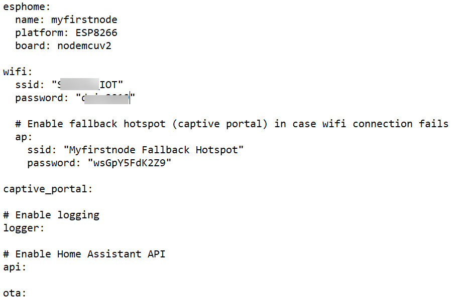
wifi:
  ssid: !secret wifi_ssid
  password: !secret wifi_key

ap:
    ssid: "CO2 meter"
    password: "1234abcd"

captive_portal: 
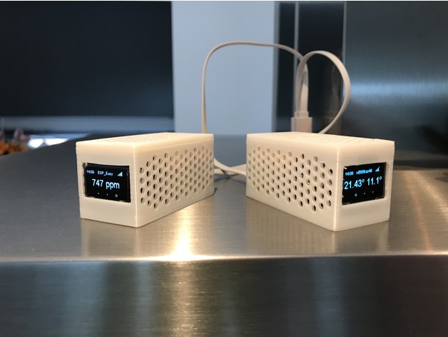
Casing

Stefan has created a nice casing for this module. Details can be found here. In the written setup ‘ESPEasy’ is used to connect the sensor. Feel free to use this, or the ESPHome implementation.

Categorieën
Home Assistant

ESPHome – Introductie

Install ESPHome

We will use ESPHome to create the binaries for the ESP8266 module. ESPHome will create a binary from a ‘YAML’ script file. ESPHome is written in Python and is using ‘PlatformIO’ to build the software. If you installed already some components, you may skip these steps.

Install Python

If you already installed Python, you should check your python version:

 python --version

It should be >2.6. If not, install python. Refer to www.python.org, current release 3.8: https://www.python.org/downloads/release/python-380/

Depending on your local OS choose Mac or Windows Web installer:

To install the Windows web-based installer, download the file and start it from the ‘Download’ directory:

Check the ‘Add Python 3.8 to PATH’ check box and choose ‘Install Now’

Choose ‘Install Now’.

After installation choose ‘Disable path length limit’ (just in case) and ‘Close’.

Check your setup by opening a CMD window entering the ‘python –version’ command:

python --version

Start the installation of esphome:

pip install esphome

This will install all the components needed.

Now you can create your first ‘YAML’ file.

Create a working directory in your home or documents directory and select this directory:

CD <documentsdir>
md esphome
cd esphome
esphome myfirst.yaml wizard

The Wizard is helpful in creating your first YAML file. First enter a chosen name for your node. This name will be broadcasted in the WiFi network, so choose a unique one!

Step 2 is asking for the platform (ESP32 or ESP8266). Choose, depending on your hardware.

In case of the workshop you should enter ESP8266, and Nodemcuv2 or d1_mini (WEMOS).

Step 3, enter your Wifi credentials (SSID and password)

In Step 4 you can enter a password for the OTA setup. In case of an untrusted network this will give you some more security

Now your YAML file will be created, it is an ASCII file which can be edited by your favourite editor (or notepad):

This file can be edited here, so any configuration changes can be done from here.

Now the magic will start. Connect an USB cable to your ESP8266 board and enter:

esphome myfirst.yaml run

This will compile your yaml file, create and upload the binary firmware to your module. Compilation will take some time, because platform and libraries should be loaded first. After compilation you get the option to upload the file:

Choose the COM port (you should first upload the code by USB). After uploading the ESP will reboot and try connect to the given SSID. The USB port will now act as a logging port and esphome will display the messages:

The Blinking Led

The Hello World example of IoT / The Embedded world. So here we go:

To configure the options from your ESP module, you have to add some lines to the YAML file. Open the YAML file with notepad or any other editor. Add the following lines:

web_server:
  port: 80
switch:
  - platform: gpio
    name: "LED"
    pin:
      number: 16
      inverted: yes

Be aware of the spacing, you should use two spaces for every intended line! 16 is the GPIO pin from the build-in LED in the NodeMCU v2 board. You should change if needed for WEMOS (GPIO pin 2).

Now you can again upload the code:

esphome myfirst.yaml run

Upload should be possible now with OTA (over the air programming). Important to check the uniqueness of your nodename. USB cable is a safe option, but give it a try.

Now try to connect to your node: http://myfirstnode , you should enter here your given name in step 1 of your project, be aware this will only work if everyone in the same network uses a different name.

Now you can toggle the LED by clicking the ‘Toggle’ button. The debug screen will give more information.

Reading a BMP280 sensor

Check out https://esphome.io/ , you see a lot of integrations possible. Choose any sensor you like, add it to some spare pins of your ESP module, add the configuration to the YAML file and here you go!

BMP280 sensor

This sensor is connected by i2c bus. Connect GND to GND, VCC to 3v3 (BEWARE: the sensor can’t handle 5V!!), SDA to D2 (Wemos) or GPIO4, SCL to D1 (Wemos) or GPIO5.

First install i2c in yaml, and then add the sensor:

i2c:
  sda: 4 #D2 Wemos
  scl: 5 #D1 Wemos
  scan: True
sensor:
  - platform: bmp280
    temperature:
      name: "BMP280 temperature"
    pressure:
      name: "BMP280 pressure"
    address: 0x76
    update_interval: 60s 

After uploading the code, the startup logging will show the i2c bus scan (due to ‘scan: true’), check if the sensor is found here:

Check if your sensor shows up here, may be you should change the address (0x76 to 0x77) depending on your hardware.

Automagically the sensor values show up in the webserver:

Publish to MQTT

To publish your data outside the ‘Home Assistant’ environment, you can use the common MQTT interface. You may use your own, local, MQTT server like Mosquito on your PI, or use a public one like ‘HiveMQ’. If you use an external service, be aware that anyone can read the results. Add the following lines to the YAML file:

mqtt:
broker: broker.hivemq.com

You should remove the ‘API’ line, or add a # (‘comment’):

# Enable Home Assistant API
#api:

After uploading, all the results from sensors, state of switches and even debugging messages are published to the MQTT server. The syntax is straight forward:

<name of your esp, as used in ‘step 1’>/sensor/bmp280_temperature/state is the topic used for the BMP temperature. You could change your ESP name to be unique.

Now you can go to http://www.hivemq.com/demos/websocket-client/ and ‘Add new Topic subscription’. If you enter here the <name of your ESP>/# , all the messages from your ESP will be shown:

NodeRed

Now we can pick up this data in other platforms, like NodeRed

Add a MQTT input node:

The topic should start with your node name. The server should be broker.hivemq.com.

If you connect a debug or gauge component, the value will be shown in your dashboard:

nl_NLDutch